Scan Region Action
Overview
The Scan Region Action enables automated inspection of parts and assemblies through programmed camera scanning patterns. This powerful action type works with Rapta SuperPod and PrecisionPod positioning systems to execute complex multi-axis scanning sequences, capturing images at precise intervals to detect defects, foreign objects/debris (FOD), or parts across large or detailed surfaces.
Version Support: Supported from V8.4.0 and later.
Quick Start: Training and Coaching a Scan Region Step
Before using the Scan Region Action, you must have a trained Part Library with entries pertaining to detections to be made on the assembly (defects, FOD, or parts).
Be sure to capture 5-6 annotated images per detection example before training.
Select the Scan Region action during assembly training to begin capturing positioning device motion instructions and assigning detection targets.
Use the CAPTURE ALL IMAGES setting to capture images regardless of detected defects or FOD. This option allows full photographic recording of the inspection process.
Activate the assembly and navigate to the Operator page to begin coaching.
Prerequisites
Before using the Scan Region Action, you must complete the following setup in your Rapta system:
Parts Library Configuration
- Navigate to the Part Library in your Rapta Supercoach supervisor interface
- Add the item to be inspected as a part in the Part Library
- Add captured images of the part features (defects, FOD, or individual parts) that you want to detect during scanning:
- Click the EDIT button on the item
- Click ADD in the Captured Images section
- Use the platform camera to capture an image showing the defect, FOD, or part
- Segment the area of interest using mouse clicks or bounding box segmentation
- Save the captured image
- Click the Plus icon on the captured image card to add an annotation
- Define and label the detection targets in the image
- Once all items have annotated training images, click TRAIN to build the detection model
For detailed instructions on Parts Library setup, see Part Verification and Part Library.
Hardware Requirements
- Rapta SuperPod or Rapta PrecisionPod positioning system installed and configured
- Motion control enabled in Setup (see Rapta SuperPod and PrecisionPod)
What Problem Does It Solve?
Traditional fixed-camera inspection requires operators to manually reposition parts or limits inspection to a single viewing angle. Scan Region automates comprehensive inspection by moving the camera through programmed scanning patterns, enabling:
- Automated defect detection across large surface areas or complex geometries
- Foreign object and debris (FOD) detection with complete coverage of inspection zones
- Reduced inspection time by eliminating manual repositioning
- Consistent inspection quality through repeatable scanning patterns
- High-value item inspection with dramatic cost reduction through automation
Key Features
Programmable Scanning Patterns – Create custom scanning sequences with multiple movements across different axes. Each scan can specify starting position, incremental steps, and ending position.
Multi-Axis Support – Coordinate movements across up to 4 axes (X, Y, Pan, Tilt) to achieve comprehensive coverage of inspection areas.
Defect Library Integration – Select from your configured defects and foreign objects in the parts library to automatically detect during scanning.
Motion Blur Elimination – The system pauses at each inspection point to capture clear images, ensuring detection accuracy throughout the scanning sequence.
Real-Time Visual Feedback – Monitor scanning progress with live camera feed showing the current inspection position as the scan executes.
How It Works
The Scan Region Action coordinates camera positioning with AI-powered defect detection:
- Program the scan – Define starting and ending positions for each scanning movement
- Configure inspection points – Set the step distance between inspection captures
- Select defects to detect – Choose which defects or foreign objects to identify during the scan
- Execute automatically – During live assembly coaching, the positioning system moves through the programmed pattern while the AI inspects at each stop point
- CAPTURE ALL IMAGES Option – Enable this option to capture images at every inspection point for complete photographic documentation. By default, images are only captured when defects, FOD, or parts are detected
All detected defects are recorded with precise position coordinates, enabling exact identification of issue locations for rework or analysis.
Creating a Scan Region Action
Adding the Action
- Navigate to your assembly in the Assembly Builder
- Click to add a new step
- Select the Scan Region action type from the available actions
- The Scan Region configuration interface will open
Configuring Defect Detection
Select Defects to Detect
- Choose from items previously added to your parts library
- Multiple items can be monitored simultaneously during a single scan
Programming Scanning Motions
The scanning interface adapts to your connected positioning system (SuperPod or PrecisionPod), showing only the available axes for your hardware configuration.
Add a Scan Sequence
- Click “Add Scan” to begin programming a new scanning pattern
- Define Starting Point – Position the camera at the beginning of the scan region either:
- Visually using the camera positioning controls
- By entering exact coordinates in the position table
- Set Step Distance – Configure how far the camera moves between inspection captures:
- X/Y axes: Distance in millimeters (default: 0mm)
- Pan/Tilt axes: Angle in degrees (default: 0°)
- Smaller steps provide more inspection points but increase scan time
- Define End Point – Position the camera at the end of the scan region
- Preview the Path – Click the play button to view the complete scanning pattern with live camera feed
- Select CAPTURE ALL IMAGES – Enable this option to capture images at all inspection points. When disabled (default), images are only captured when defects, FOD, or parts are detected
Multiple Scan Sequences Complex inspection patterns can combine multiple sequential scans. For example:
- Vertical scan from top to bottom
- Followed by rotational movement
- Followed by another vertical scan from a different angle
Add as many scan sequences as needed to achieve complete coverage of your inspection area.
Advanced Configuration
Zoom Control – Adjust digital zoom on the camera to optimize inspection detail level for your application.
Duplicate Scans – Use the duplicate button to create variations of existing scanning patterns quickly.
Edit Position Tables – Fine-tune any scan by directly editing position values in the configuration table.
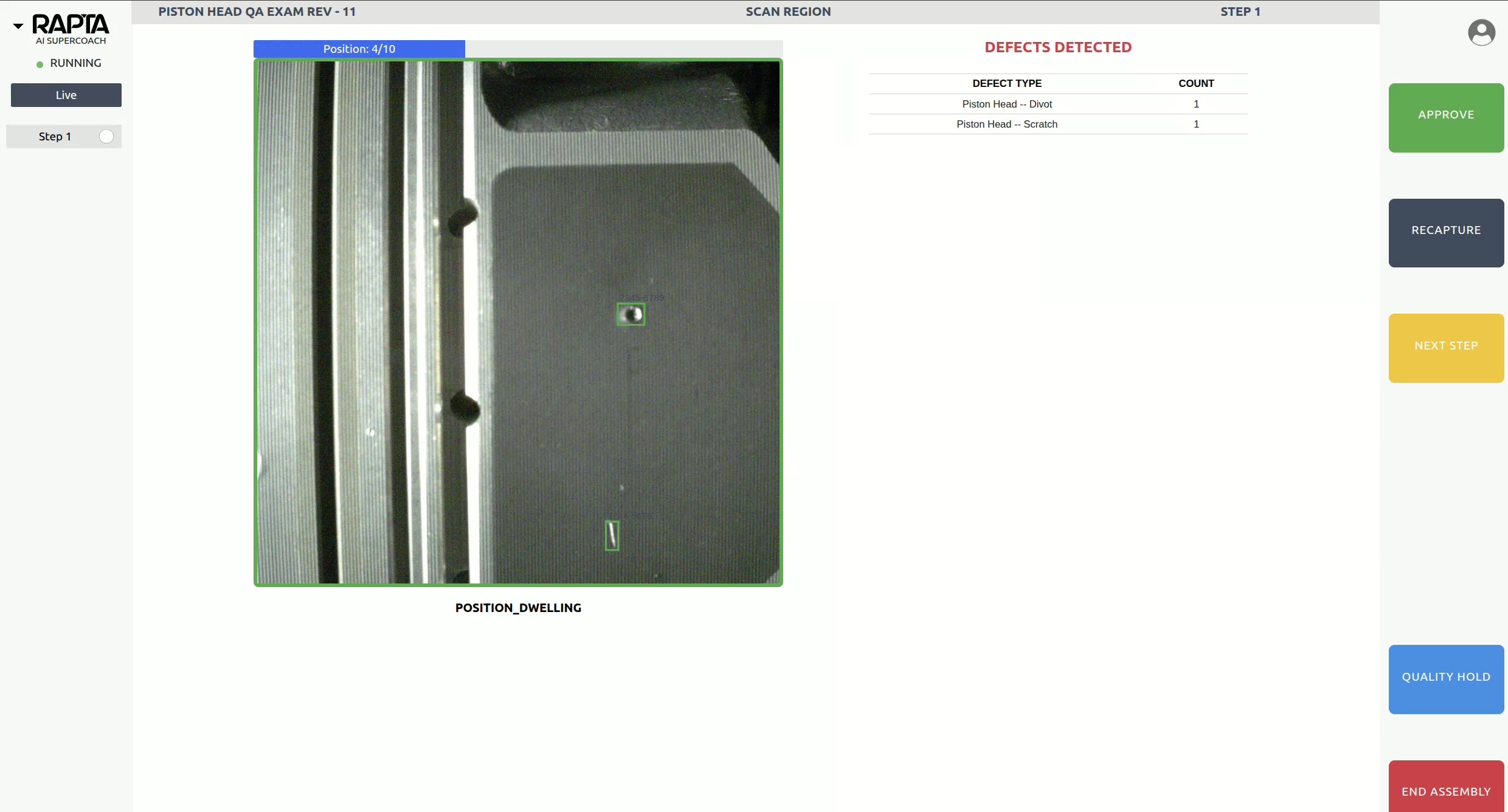
Using Scan Region in Live Assembly
During coaching (live assembly execution):
- The positioning system automatically executes the programmed scanning pattern
- The camera feed updates in real-time showing current inspection position
- The system pauses at each inspection point to capture and analyze images
- Detected defects, FOD, or parts are highlighted with green bounding boxes around them
- Any detected defects trigger immediate notification to the operator
- The exact position coordinates of detected defects are recorded
- The system completes all programmed scans before advancing to the next step
Inspection Reports
Scan Region Actions provide comprehensive documentation in assembly reports:
Defect Location Data – Each detected defect includes precise position coordinates indicating the position of the camera when the issue was found on the inspected part.
Complete Image Capture – All images captured during the scanning sequence are included in the report appendix, providing photographic documentation of the inspection.
Traceability – Every scan is tied to the specific serial number, part number, and date code for complete quality traceability.
Hardware Requirements
Required Equipment
- Rapta SuperPod or Rapta PrecisionPod positioning system
- Compatible camera mounted to positioning system
- Network connectivity between Rapta station and positioning hardware
System Configuration
- Motion control must be enabled in Setup (see SuperPod and PrecisionPod setup)
- Positioning system must complete homing sequence before first use
- Connection status verified via “Test Connection” in Setup
Best Practices
Defect Library Preparation
- Configure defects, FOD, and parts in the Parts Library before creating Scan Region actions
- Capture sufficient training images with annotations for each detection target (6-10 images recommended)
- Use clear, descriptive names for items to simplify selection during configuration
- Regularly review and update definitions based on inspection results
- Retrain the Parts Library model after adding new items or images
Optimize Scan Patterns
- Design scanning paths that provide complete coverage without excessive overlap
- Balance step distance with inspection requirements – smaller steps increase scan time but improve detection
- Test scanning patterns thoroughly during assembly creation before deploying to production
Verification and Testing
- Always use the preview function to verify scanning paths before saving
- Run test assemblies with sample parts to validate defect detection accuracy
- Monitor initial production runs to ensure scan patterns achieve desired coverage
Integration with Other Actions
Scan Region Actions can be combined with other Rapta assembly actions to create comprehensive workflows:
- General Assembly steps before scanning to verify correct part placement
- OCR Verification to confirm part numbers before automated inspection
- Data Capture to record serial numbers associated with inspection results
- QA Inspection steps after scanning for additional verification
Troubleshooting
Scan Not Executing
- Verify motion control is enabled in Setup
- Check positioning system connection using “Test Connection”
- Ensure all safety interlocks are satisfied (doors closed, emergency stop released)
Defects or FOD not being detected:
- Verify you have added annotations to captured images using the Plus icon feature
- Ensure sufficient annotated training images exist for each detection target (6-10 recommended)
- Check that annotations accurately cover the defects or FOD in the training images
- Retrain the object detection model after adding new annotations
- Verify camera position, zoom, and lighting provide adequate view during inspection
Related Articles
- Part Verification and Part Library
- Rapta SuperPod and PrecisionPod
- Assembly Actions
- QA Inspection
- Best Practices Creating Assemblies
For additional support or questions about Scan Region Actions, contact your Rapta support team.