Installation Guide
Congratulations on purchasing a Rapta AI Station! This guide will walk you through setup and installation of the system in your facility. The Rapta AI system is designed to be flexible to suit your application environment. Many customers choose to use their existing frames or fixtures and in many cases this works well. Contact our Support Team to find out if this is compatible with the Rapta AI Inspection system.
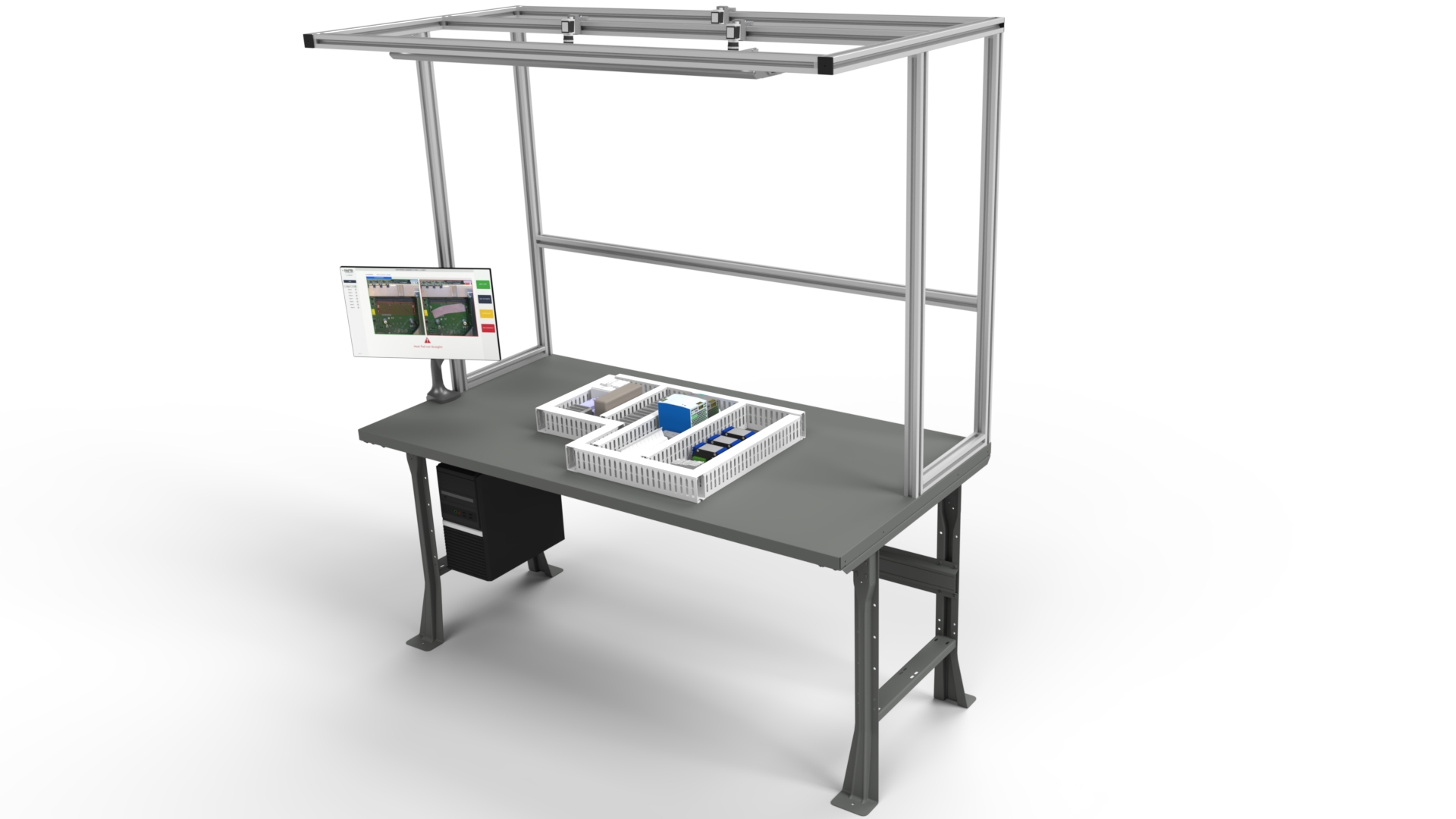
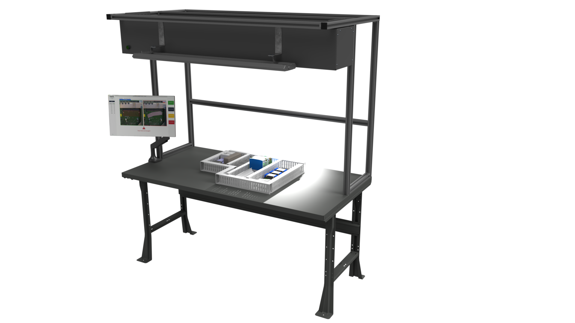
Table of Contents
Typical installation time
This production stand can be installed in 1 – 2hrs with one to two experienced technicians.
Required tools
The following tools are required to install the production stand:
- 2.5mm Allen Key (ball end preferable)
- 3mm Allen key (ball end preferable)
- 4mm Allen key (ball end preferable)
- 6mm Allen key (ball end preferable)
- Small flat head screwdriver
- #2 Philips driver
- Needle nose pliers
- Spirit level
Assembly Drawings
The Production Stand ships flat-pack to your site and requires assembly with the minimum tools listed above. You will need to mount the Rapta stand on a sturdy workbench.
Multi Camera Station
SuperPod Station
Installing the Frame
The following details the basic parts required for mounting the cameras and light assembly. RoboUnits is the suggested vendor; however we have customers using T-Slots, Rexroth, 8020 and many other frame types successfully in production environments. We recommend permanently bolting the frame to the benchtop.
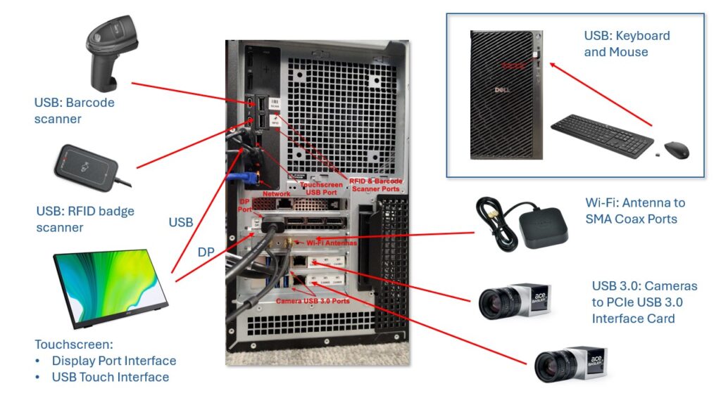
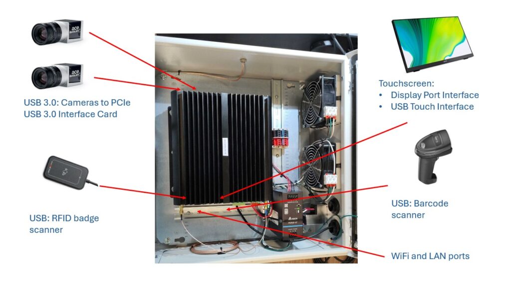
Connecting the AI Computer and peripherals
Rapta’s software runs on commercial or industrial grade x86 processors. Here is a list of common interfaces:
- Cameras: USB 3.0 or Ethernet (requires a PoE switch)
- RFID Reader: USB 2.0+
- Touchscreen: Display port + USB
- Barcode Scanner: USB 2.0+
- Keyboard + Mouse: USB 2.0+
Commercial PC Multi Camera Station
Industrial PC Multi Camera Station
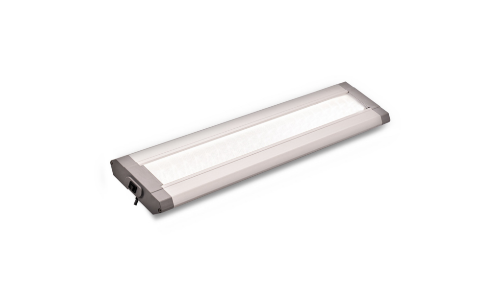
Installing the Light
Standard Rapta kits often include an overhead work light to illuminate the work area for the cameras. The station drawings above show how the light is typically positioned with the supplied bracket mounting kit. The light includes a pre-wired power supply that can be plugged into a standard 120VAC outlet and consumes 48W. Please refer to Correct Lighting Setup for detailed information on lighting best practices.
Installing the Cameras
Multi-camera Rapta systems use a mount and wedge system to permanently position the camera for your application needs.
Downloads for Mounting Brackets
The camera brackets and camera angle wedges can be downloaded and 3D printed from this link: Downloads
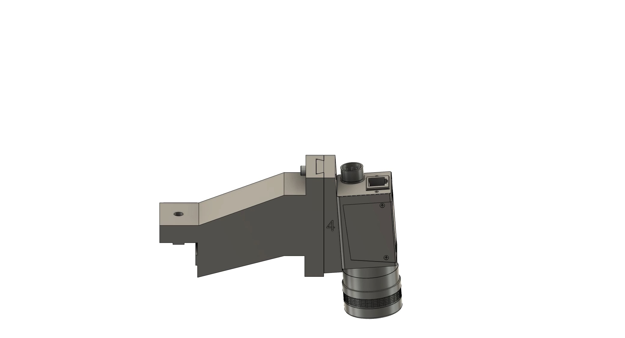
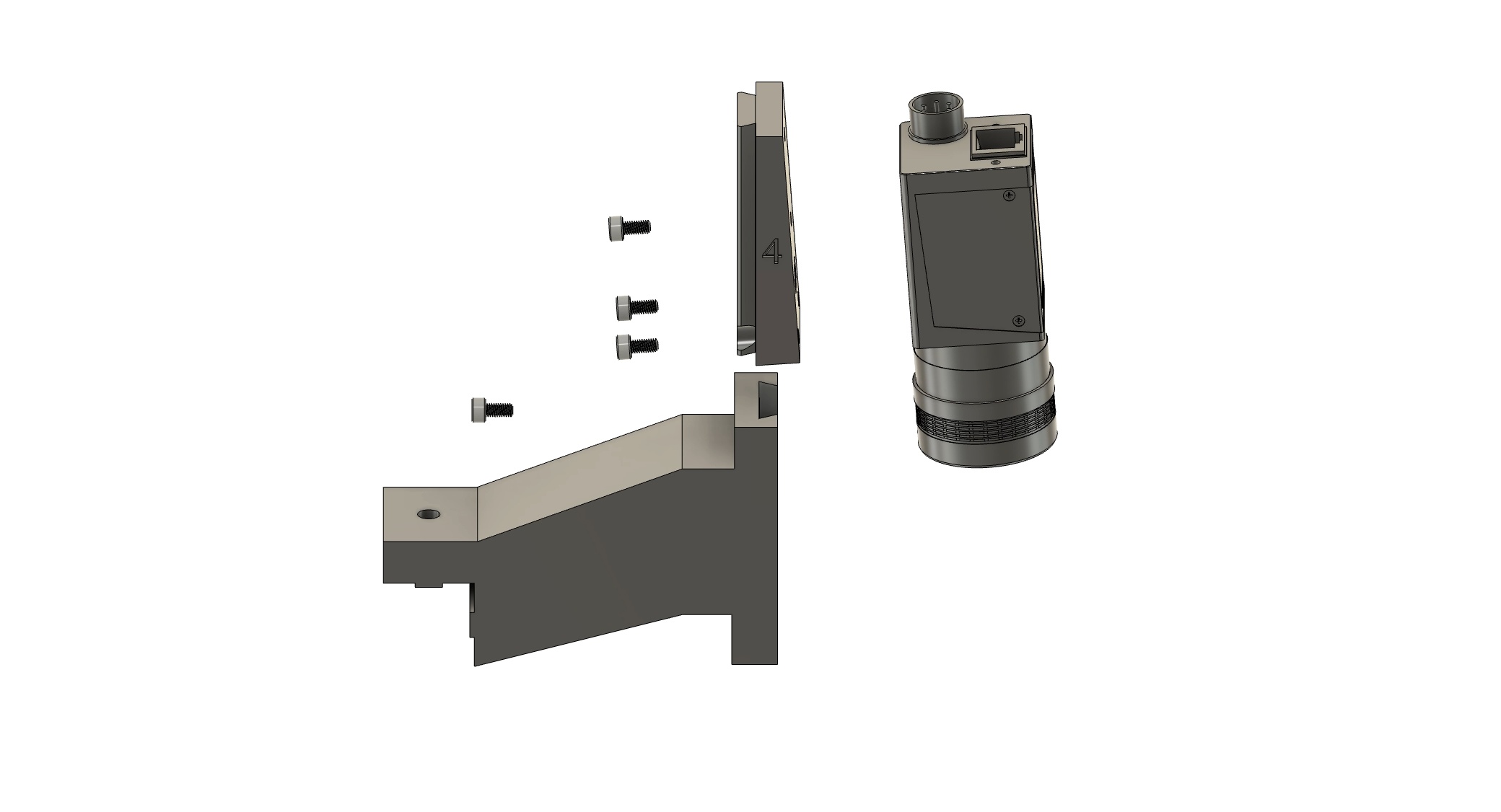
Installing the camera onto the mount
Video instruction showing how to install the camera on the mount is featured below, the key steps include:
- Screw the “wedge” to the camera body with the 3 x M3 6mm mounting screws.
- Slide the wedge into the mount, noting there is a 3mm hole where the locking screw inserts through.
- Insert the M3 screw into the back of the mount to lock the wedge and camera into place.
Verify the camera angle and position
Navigate to the camera setup tab to verify the camera is correctly positioned for your assembly. If the image is not clear or distorted, refer to the Camera setup procedure.
Adjust camera angle
Video instruction showing how to uninstall the camera from the mount is featured below, the key steps include:
- Remove the M3 screw from the back of the mount that locks the wedge and camera into place.
- Slide the wedge out of the mount gently supporting the mount with one hand.
- Unscrew the “wedge” from the camera body by removing the 3 x M3 6mm mounting screw.
Camera Lens Selection
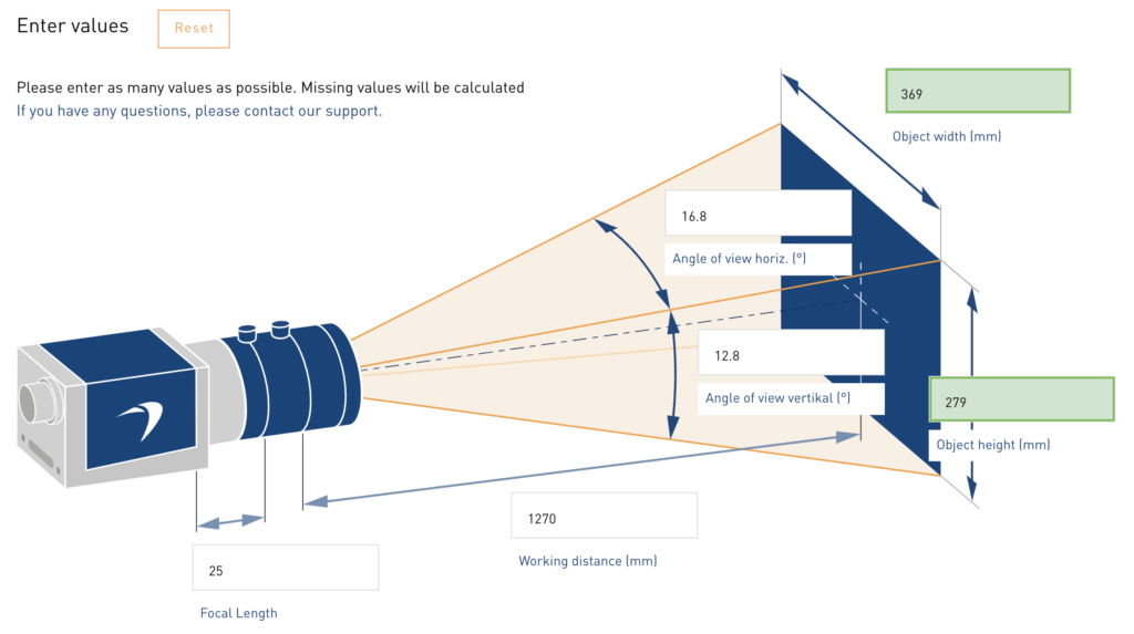
Selecting the right lens for your application involves the following key considerations.
- Working distance: This is the distance between the camera lens and the application. Rapta typically mounts the camera at between 1ft (300mm) and 4ft (1300mm) from the application, however this can vary depending upon your requirements.
- Focal length: This is the lens focal length and in a typical application this will be 8mm, 12mm, 16mm or 25mm. The focal length and working distance drive the object or viewable area and the number of pixels per square inch (or square centimeter). The higher the focal length (eg 25mm), the higher the magnification.
Most high quality industrial camera manufacturers provide a comprehensive lens selector to aid this process, here is one example using the Basler lens selector.
Camera Lens Aperture Adjustment
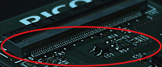
Once the camera is mounted with the lens installed, the next step is to adjust the lens aperture. The lens aperture is a critical driver of the depth of field (DOF) and the amount of light entering through the lens. Below is an example on the left where text on a PCBA is visible across the board with the aperture set to provide sufficient depth of field. The example on the right shows poor depth of field so text or objects in the scene are out of focus. Poor depth of field will impact the performance of AI if you are trying to recognize any of the objects in that scene or perform OCR validation.

Camera Lens Focus Adjustment
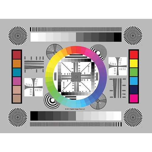
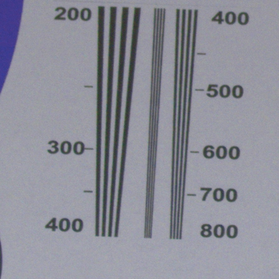
The very last step in the process is focus adjustment. This is aided by a calibration card with many available, here is one example.
Focus adjustment process:
- First rotate the focus until you see the image come into focus, then go past that point until it’s blurry again. Then turn back the focus to the point where it is no longer blurry.
- Zoom into a region where there is small text and verify the text is all visible. Repeat this process for objects of different heights or distances from the camera to make sure each region of interest in the camera scene is in focus.
Camera Calibration
Rapta’s system includes automatic adjustment of the camera white balance, color, gain and other parameters to ensure it is setup correctly for your application. Then run this process, select Auto Adjust Camera from the Setup tab.
Important Note: It’s critical you perform Auto Adjust with a white background, putting a piece of white paper in front of the camera is a good way to ensure that the camera is auto adjusting with the correct white balance. If you use another dominant color such as a blue anti-static mat, the color adjustment will be off. Further information can be found in this article Camera Color Calibration.
Installation Complete
Congratulations, you have successfully installed the Rapta AI Inspection station. You’re ready to start building your first assembly! Read this article for next steps follow this page, Assembly Actions.